RC Bronco Controller/Receiver Build
About this project
A few months ago, I made the unfortunate discovery that my 1/24 RC Bronco had bit the dust. The first drive after a year or so of sitting on the shelf revealed that the car only wanted to drive backward. Rather than spend the $30 on a new off-the-shelf controller/receiver module, I decided to take a stab at designing my own.
This post is the first in a 3 part series that will follow my process in building a custom controller/receiver for this car.
For starters, here is an image of the factory ESC/Receiver that I’ll be replacing: 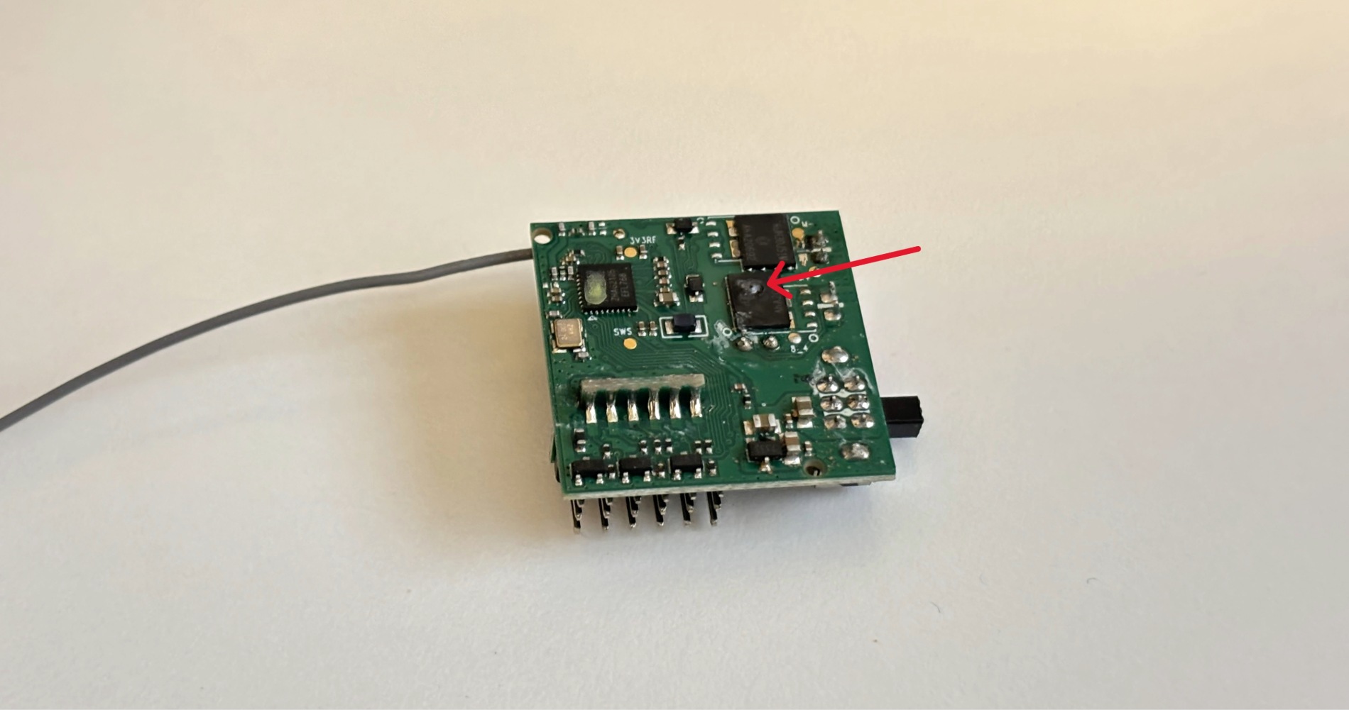 As you can see, there is practically a hole burned through this MOSFET.
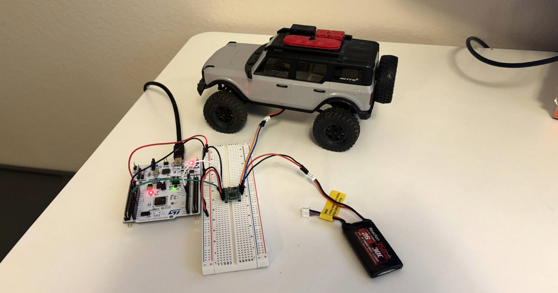
These are the components that will be used in this first stage of development:
- STM32 Nucleo L476RG
- Pololu DRV8874 DC Motor Driver module
- 7.4V LiPo battery
- 1/24 Horizon Hobby Ford Bronco
- Breadboard
Wiring
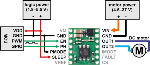
The DRV8874 has a few requirements for setup, but is very straightforward to use. As shown in the image below, the SLEEP pin is set to high using the 3.3V from the STM32. The PMODE pin is set low (tied to ground) which enables the controller to run in its most basic setting, PH/EN mode. Using this setting, I can send either a high or low signal to the PH pin to control the direction of the motor. PWM signals to the EN pin control the motor speed. On the other side of the module, VIN and GND are connected to the battery and OUT1 and OUT2 are connected to the motor.
Configuring STM32
Moving on to programming the STM32, I begin by configuring the two output pins needed for sending direction and speed signals to the controller. Pin PB10 is set to GPIO output and will be used to set the direction of the motor.
To configure a pin to be used in generating PWM signals, I begin by adding a timer. I set this timer to have a counter period of 255, a prescaler of 79 and a pulse of 75. The timer is set to auto-reload.
Programming
Within the main.c file, I added the following code to test the motor controller:
1
2
3
4
5
6
7
8
9
10
11
12
13
14
15
16
  while (1)
  {
    HAL_GPIO_WritePin(GPIOB, GPIO_PIN_10, GPIO_PIN_SET);
    __HAL_TIM_SET_COMPARE(&htim2, TIM_CHANNEL_1, 75);
    HAL_Delay(1000);

    __HAL_TIM_SET_COMPARE(&htim2, TIM_CHANNEL_1, 0);
    HAL_Delay(1000);

    HAL_GPIO_WritePin(GPIOB, GPIO_PIN_10, GPIO_PIN_RESET);
    __HAL_TIM_SET_COMPARE(&htim2, TIM_CHANNEL_1, 75);
    HAL_Delay(1000);

    __HAL_TIM_SET_COMPARE(&htim2, TIM_CHANNEL_1, 0);
    HAL_Delay(1000);
  }
This code simply sends PWM signals of 75% to the DRV8874, alternating directions, with a one second delay in between.
After compiling and uploading to the board, the car now successfully moves forward and backward in an endless loop.